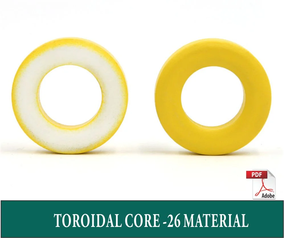
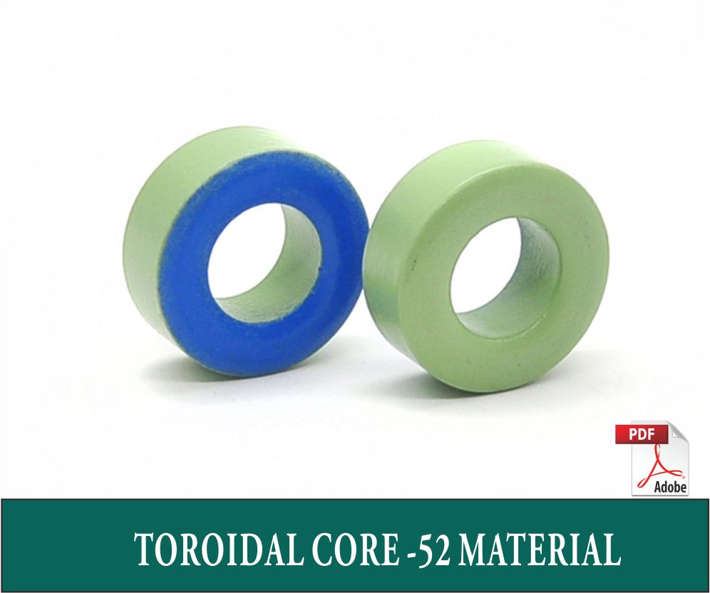
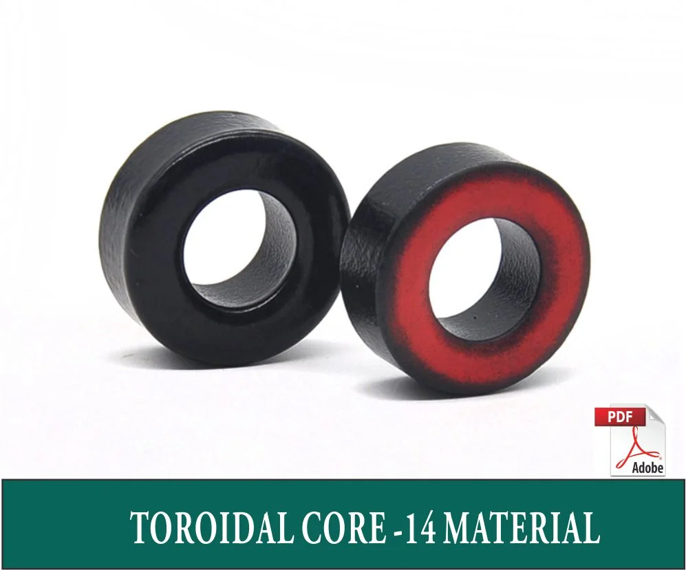
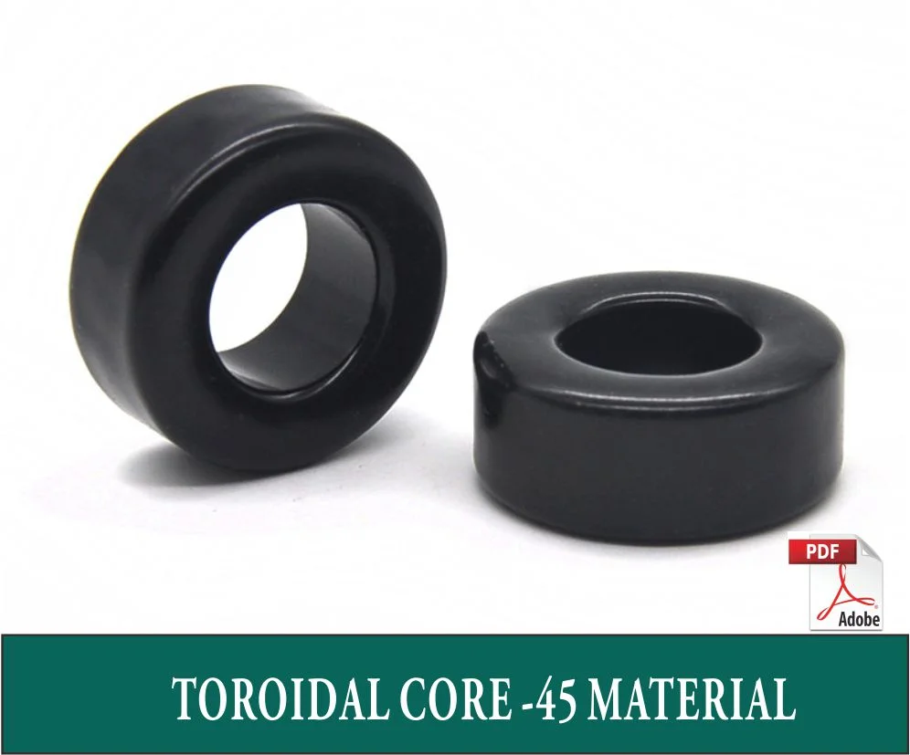
What is, and why using Iron Powder Cores?
Iron powder cores are commonly used in power conversion, line filter applications and radio frequency applications. Oftentimes, iron powder cores substitute ferrite cores. Ferrite cores have a high permeability so it needs an air gap to reduce this permeability. This air gap has the disadvantage of power loss, leading to the risk of a hot spot.
Iron powder cores do not need the additional air gap. The characteristics of iron powder cores reduce the power loss. Furthermore, the saturation flux density in ferrite cores is around 400 mT and decreases with temperature. Iron powder cores have the saturation flux densities of more than 1T.
VIEW OUR PRODUCTS
iNTERESTED IN LEARNING MORE ABOUT IRON POWER CORES? read THE INFORMATION from our supplier
Temperature Characteristics
Iron powder cores typically function under the temerature between -65°C~ +125°C. If the operating temperature is above 150°C,the organic epoxy-resin binder starts to decompose, resulting in characteristics degradation in terms of temperature rise (watt losses),DC bias as well as life time. Such pheomon really depends on operating time period, temperature, core size, switching frequency and the flux density.
Surface Coating
The toroidal cores listed in this catalogue are epoxy-coated. All finishes can resist most cleaning solvents. Extended exposures to certain solvents may have detrimental effects. The E cores and the U cores are treated to resist corrosion. Coating is tested at 50Hz, 1250Vrms for 5 seconds to meet the minimum dielectric strength(Hi-pot test).The toroidal cores can be double or triple coated for greater dielectric strength.
Magnetic Tolerance
Cores are manufactured based on their AL values within certain tolerance. The permeability of each material is only for reference. AL value is tested under 10kHz and 10G(or 1mT) at all time. For toroids, winding should be fully and evenly distributed throughout the core to minimize the leakage inductance. Iron powder toroidal cores will always have higher inductance measurement reading than expected if the number of turns is low resulting in winding not evenly distributed throughout the core. For E-cores,100 turns will be used as the standard testing criteria. The typical tolerance of AL value shown above is ±10% while the tolerance of core loss curve for the above listed materials is ±15%。


